GDI+画线算法
我无法理解 GDI+ 在表面上画线的方式,可能它有一些算法来做到这一点。
对于前。让我们取一个 10x10 像素的表面。
Bitmap img = new Bitmap(10, 10);
现在让我们在这个表面上画一条线,宽度为 5px,顶部偏移量为 5px。
  using (var g = Graphics.FromImage(img))
     {
        g.Clear(Color.White);
        var pen = new Pen(Color.Brown);
        pen.Width = 5;
        g.DrawLine(pen, 0F, 5F, 10F,  5F);
     }
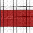
我们将得到:

绘图不是从像素 #5 开始,而是从像素 #4 开始。 显然,起点是单独计算的。但如何呢?
我试图获得规律性,并得到了这个:
y = offset + width/2 - 1
其中 y 是真实的起点 y,偏移量是选定的起点 y。
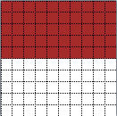
但在某些情况下这不起作用。例如,让我们取宽度=6,选择顶部偏移=0,我们将得到y=2,并且它将以这种方式绘制:

它必须显示 6 像素,但事实并非如此。
所以必须有更通用的算法来选择起点,但我真的不知道它会是什么。 任何帮助表示赞赏。
I cannot understand the way GDI+ is drawing line on a surface, may be it has some algorithm to do it.
For ex. lets take a surface 10x10 px.
Bitmap img = new Bitmap(10, 10);
Now lets draw a line on this surface, with width 5px and top offset 5px.
  using (var g = Graphics.FromImage(img))
     {
        g.Clear(Color.White);
        var pen = new Pen(Color.Brown);
        pen.Width = 5;
        g.DrawLine(pen, 0F, 5F, 10F,  5F);
     }
We will get:

The drawing didn't begin at pixel #5, it began from pixel #4.
It is obvious, that the start point is calculated separately. But how?
I've tried to get a regularity, and got this:
y = offset + width/2 - 1
where y is real start point y, offset is selected start point y.
But in some cases this doesn't work. For example, lets take width=6, selected top offset = 0, we will get y=2, and it will be drawn this way:

It must show 6 pixels but it didn't.
So there must be more general algorythm for selecting the start point, but I really have no idea aboit what it can be.
Any help appreciated.
如果你对这篇内容有疑问,欢迎到本站社区发帖提问 参与讨论,获取更多帮助,或者扫码二维码加入 Web 技术交流群。

绑定邮箱获取回复消息
由于您还没有绑定你的真实邮箱,如果其他用户或者作者回复了您的评论,将不能在第一时间通知您!

发布评论
评论(3)
线条图中没有
偏移。您在DrawLine方法中指定的坐标定义了线条的中心。顶部像素为y - width / 2,底部像素为y - width / 2 + width - 1。第二个公式考虑了width / 2向下舍入的事实。另外,顶行是y = 0,底行是y = 9。因此,对于第一行:和第二行:
顶部边缘被剪切到位图的边缘,因此线宽减小。
There is no
offsetin the line drawing. The co-ordinates you specify in theDrawLinemethod define the centre of the line. The top pixel isy - width / 2and the bottom isy - width / 2 + width - 1. That second formula takes into account the fact thatwidth / 2is rounded down. Also, the top line isy = 0and the bottom line isy = 9. So, for you first line:and the second line:
The top edge is clipped to the edge of the bitmap so the line width is reduced.
在第一个示例中,它看起来像一条宽度为 5 个像素的线,以第 5 行为中心(从 0 开始计数,而不是从 1 开始)。
这似乎是一个合理的结果。
在第二个示例中,它看起来像一条宽度为 6 的线,位于第 1 行和第 2 行之间的中心,其中顶行被切断,因为它延伸到图像的边界之外。
In the first example, it looks like a line with a width of 5 pixels, centered on row 5 (counting starts at 0, not 1).
This seems like a reasonable outcome.
In the second example, it looks like a line of width 6, centered between rows 1 and 2, where the top row is cut off, because it extends beyond the borders of the image.
GDI+ 中的坐标并不指定像素本身,而是指定像素中心的(无限小)点。因此
(0f,5f)表示第一列第六行的像素中心(因为计数从零开始)。因此,从现在开始我将区分坐标和像素行。绘制线条时,GDI+ 从概念上讲会沿着这些坐标定义的线条移动指定宽度的笔。请注意,您可以通过指定
Pen.StartCap和Pen.EndCap来定义该笔在线条开头和结尾处的确切形状。由于您指定了宽度
5f并且正在绘制一条水平线,因此该线将2.5像素延伸到顶部和底部,从而覆盖从 #3 到 (并包括)#7。请注意,根据以下公式,像素行 #3 的上边缘的 y 坐标为2.5,行 #7 的下边缘的 y 坐标为7.5。上面的定义,分别是5f-2.5f和5f+2.5f对于第二个示例,我没有得到与您相同的结果(我在 尝试 GDI+ 应用程序)。相反,我得到一条覆盖前三个像素行的线。理论上,它甚至应该覆盖前 3.5 个船头(因为坐标指定第一行的中心,所以上部部分被简单地剪掉)。但如果关闭抗锯齿功能,底部的“半行”就会被截断。
这可以通过将
g.SmoothingMode设置为SmoothingMode.AntiAlias来显示,在这种情况下,第四行将透明绘制。使用抗锯齿功能时,您还会注意到,第一列和最后一列未完全绘制,因为起始坐标再次位于列的中心。Coordinates in GDI+ don't designate the pixels itself but the (infinitly small) points at their center. Thus
(0f,5f)means the center of the pixel in the first column and 6th row (since counting starts at zero). Therefore, I will differentiate between coordinates and pixel rows from now on.When drawing a line, GDI+ conceptually moves a pen of the specified width along the line defined by these coordinates. Note that you can define the exact shape of this pen at the beginning and the end of the line by specifying
Pen.StartCapandPen.EndCap.Since you specified width
5fand you're drawing a horizontal line, the line extends2.5pixels to the top and to the bottom thus covering complete pixel rows from #3 to (and including) #7. Note that the upper edge of pixel row #3 has a y-coordinate2.5and the lower edge of row #7 has7.5according to the above definition, which is5f-2.5fand5f+2.5frespectivelyI do not get the same result as you for your second example (I tried in Try GDI+ application). Instead I get a line which covers the first three pixel rows. Theoretically, it should even cover the first 3.5 prows (since the coordinate designates the center of the first row, the upper part is simply clipped). But if antialiasing is turned off, the 'half row' at the bottom gets truncated.
This can be shown by setting
g.SmoothingModetoSmoothingMode.AntiAliasin which case the fourth row is drawn transparently. When using antialiasing you'll also notice, that the first and last column are not completely painted since the start coordinate is, again, at the center of the column.