常量缓冲区中的纹理变换矩阵无法正常工作
我尝试通过 0 和 1 对纹理坐标进行硬编码来剪辑纹理,然后将包含 3x3 纹理变换矩阵的常量缓冲区发送到顶点着色器。
然而,纹理并没有像我预期的那样渲染。我不确定我哪里出错了。有人可以帮忙吗?请参阅下面的代码。
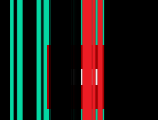
为了进行测试,我尝试使用单位矩阵来保持纹理坐标不变,但纹理显示以一种非常奇怪的方式进行转换。
这是纹理:(除了黑色和心形较柔和的红色之外,显示的颜色实际上是透明区域)

转换纹理:

HLSL:
cbuffer cbChangesPerFrame : register( b0 )
{
    matrix g_Mvp;
};

cbuffer cbTexTransform : register( b2 )
{
    float3x3 g_TexTransform;
};

Texture2D g_ColorMap : register(t0);
SamplerState g_ColorSampler : register(s0);

struct VS_Input
{
    float4 pos : POSITION0;
    float2 tex0 : TEXCOORD0;
};

struct PS_Input
{
    float4 pos : SV_POSITION0;
    float2 tex0 : TEXCOORD0;
};

PS_Input VS_Main(VS_Input vertex)
{
    PS_Input vsOut = (PS_Input)0;
    vsOut.pos = mul(vertex.pos,g_Mvp);

    //vsOut.tex0 = vertex.tex0;
    float3 coord = float3(vertex.tex0, 1.0);
    coord = mul(coord, g_TexTransform);
    vsOut.tex0 = coord.xy ;

    return vsOut;
}

float4 PS_Main( PS_Input frag ) : SV_TARGET
{
    return g_ColorMap.Sample( g_ColorSampler, frag.tex0 );
}
VBuffer 硬编码:
Vertex::PosTex vertices[]=
{
    {XMFLOAT3( 0.5f, 0.5f, 1.0f ),  XMFLOAT2( 1.0f, 0.0f )},
    {XMFLOAT3( 0.5f, -0.5f, 1.0f ), XMFLOAT2( 1.0f, 1.0f )},
    {XMFLOAT3( -0.5f, -0.5f, 1.0f ), XMFLOAT2( 0.0f, 1.0f )},

    {XMFLOAT3( -0.5f, -0.5f, 1.0f ), XMFLOAT2( 0.0f, 1.0f )},
    {XMFLOAT3( -0.5f, 0.5f, 1.0f ), XMFLOAT2( 0.0f, 0.0f )},
    {XMFLOAT3( 0.5f, 0.5f, 1.0f ),  XMFLOAT2( 1.0f, 0.0f )}
};
矩阵定义:
XMFLOAT3X3 f3x3;
f3x3.m[0][0] = 1.0f;    f3x3.m[0][1] = 0.0f;    f3x3.m[0][2] = 0.0f;
f3x3.m[1][0] = 0.0f;    f3x3.m[1][1] = 1.0f;    f3x3.m[1][2] = 0.0f;
f3x3.m[2][0] = 0.0f;    f3x3.m[2][1] = 0.0f;    f3x3.m[2][2] = 1.0f;
GAME_MANAGER->GMSetTexTransformMatrix(f3x3);
Game_Manager GMSetTransformMatrix() 定义:
void GameManager::GMSetTexTransformMatrix( const XMFLOAT3X3& rkTexTransform )
{
    m_pContext->UpdateSubresource(m_pTexTransformCB,0,0,&rkTexTransform,0,0);
    m_pContext->VSSetConstantBuffers(2,1,&m_pTexTransformCB);
}
缓冲区初始化:
ZeroMemory(&constDesc, sizeof(constDesc));
constDesc.BindFlags = D3D11_BIND_CONSTANT_BUFFER;
constDesc.ByteWidth = 48;
constDesc.Usage = D3D11_USAGE_DEFAULT;

result = m_pDevice->CreateBuffer(&constDesc,0,&m_pTexTransformCB);
I'm trying to clip a texture by hardcoding the texture coordinates through 0 and 1, and then sending a constantbuffer containing a 3x3 texture transform matrix to the vertexshader.
However, the texture is not rendering as I expected it to. I'm not sure where I went wrong. Could someone help? See code below.
For testing, I'm trying to use an Identity matrix to keep the texture coordinates untouched, but the texture shows up transformed in a very weird way.
This is the texture: (the colours showing up are actually transparent areas, except the black colour and the softer red colour of the heart)

Transformed texture:

HLSL:
cbuffer cbChangesPerFrame : register( b0 )
{
    matrix g_Mvp;
};

cbuffer cbTexTransform : register( b2 )
{
    float3x3 g_TexTransform;
};

Texture2D g_ColorMap : register(t0);
SamplerState g_ColorSampler : register(s0);

struct VS_Input
{
    float4 pos : POSITION0;
    float2 tex0 : TEXCOORD0;
};

struct PS_Input
{
    float4 pos : SV_POSITION0;
    float2 tex0 : TEXCOORD0;
};

PS_Input VS_Main(VS_Input vertex)
{
    PS_Input vsOut = (PS_Input)0;
    vsOut.pos = mul(vertex.pos,g_Mvp);

    //vsOut.tex0 = vertex.tex0;
    float3 coord = float3(vertex.tex0, 1.0);
    coord = mul(coord, g_TexTransform);
    vsOut.tex0 = coord.xy ;

    return vsOut;
}

float4 PS_Main( PS_Input frag ) : SV_TARGET
{
    return g_ColorMap.Sample( g_ColorSampler, frag.tex0 );
}
VBuffer hardcoded:
Vertex::PosTex vertices[]=
{
    {XMFLOAT3( 0.5f, 0.5f, 1.0f ),  XMFLOAT2( 1.0f, 0.0f )},
    {XMFLOAT3( 0.5f, -0.5f, 1.0f ), XMFLOAT2( 1.0f, 1.0f )},
    {XMFLOAT3( -0.5f, -0.5f, 1.0f ), XMFLOAT2( 0.0f, 1.0f )},

    {XMFLOAT3( -0.5f, -0.5f, 1.0f ), XMFLOAT2( 0.0f, 1.0f )},
    {XMFLOAT3( -0.5f, 0.5f, 1.0f ), XMFLOAT2( 0.0f, 0.0f )},
    {XMFLOAT3( 0.5f, 0.5f, 1.0f ),  XMFLOAT2( 1.0f, 0.0f )}
};
Matrix definition:
XMFLOAT3X3 f3x3;
f3x3.m[0][0] = 1.0f;    f3x3.m[0][1] = 0.0f;    f3x3.m[0][2] = 0.0f;
f3x3.m[1][0] = 0.0f;    f3x3.m[1][1] = 1.0f;    f3x3.m[1][2] = 0.0f;
f3x3.m[2][0] = 0.0f;    f3x3.m[2][1] = 0.0f;    f3x3.m[2][2] = 1.0f;
GAME_MANAGER->GMSetTexTransformMatrix(f3x3);
Game_Manager GMSetTransformMatrix() definition:
void GameManager::GMSetTexTransformMatrix( const XMFLOAT3X3& rkTexTransform )
{
    m_pContext->UpdateSubresource(m_pTexTransformCB,0,0,&rkTexTransform,0,0);
    m_pContext->VSSetConstantBuffers(2,1,&m_pTexTransformCB);
}
Buffer Initialisation:
ZeroMemory(&constDesc, sizeof(constDesc));
constDesc.BindFlags = D3D11_BIND_CONSTANT_BUFFER;
constDesc.ByteWidth = 48;
constDesc.Usage = D3D11_USAGE_DEFAULT;

result = m_pDevice->CreateBuffer(&constDesc,0,&m_pTexTransformCB);
如果你对这篇内容有疑问,欢迎到本站社区发帖提问 参与讨论,获取更多帮助,或者扫码二维码加入 Web 技术交流群。

绑定邮箱获取回复消息
由于您还没有绑定你的真实邮箱,如果其他用户或者作者回复了您的评论,将不能在第一时间通知您!


发布评论
评论(1)
问题是16字节对齐。 XMFLOAT3X3 只是连续 9 个浮点数。当它存储在寄存器中时,它只会取出前四个浮点数并将它们放入 c0,接下来的四个浮点数放入 c1,剩余的浮点数放入 c2.x。您可以通过以下内容亲自看到这一点:
现在,当您传递 XMFLOAT3X3 时,纹理会正常显示。问题是,由于寄存器分配,你的纹理变换矩阵被搞砸了。当您查看寄存器时,这就是您的数据的输入方式:
float3x3 可能是 float3 的数组,因此它将采用每个寄存器的前三个分量,为您提供:
它将 Y 缩放为 0,这给出了奇怪的有弹性的外观。为了解决这个问题,您要么必须将变换存储在 4x4 矩阵中,要么手动分配寄存器的每个部分。切换到三个 float3 也不起作用,因为它们无法跨越 16 字节边界。
The problem is the 16 byte alignment. An XMFLOAT3X3 is just 9 floats in a row. When this gets stored in registers, its just going to take the first four floats and put them in c0, the next four in c1, and the remaining float in c2.x. You can see this yourself with the following:
Now when you pass your XMFLOAT3X3, the texture appears normally. The problem was that because of the register allocation, your texture transform matrix became screwed up. When you look at the registers, this is how your data looks coming in:
float3x3's are probably an array of float3's, so it would take the first three components of each register, giving you:
Its scaling your Y to 0, which is giving that wierd stretchy look. To solve this, you're going to either have to store your transform in a 4x4 matrix, or manually assign each part of the register. Switching to three float3's wouldn't work either, because they can't cross the 16-byte boundary.