如何在OpenGL中实现世界坐标对齐的重复纹理映射?
当您在 3D 地图编辑器(例如 Valve 的 Hammer Editor)中创建画笔时,默认情况下会重复对象的纹理并与世界坐标对齐。
如何使用 OpenGL 实现此功能?
可以使用 glTexGen 来实现此功能吗?
或者我必须以某种方式使用纹理矩阵吗?
如果我创建 3x3 盒子,然后就很简单了: 将 GL_TEXTURE_WRAP_T 设置为 GL_REPEAT 将边缘处的纹理坐标设置为 3,3。
但如果物体不是轴对齐的凸包,它就会变得,呃,有点复杂。
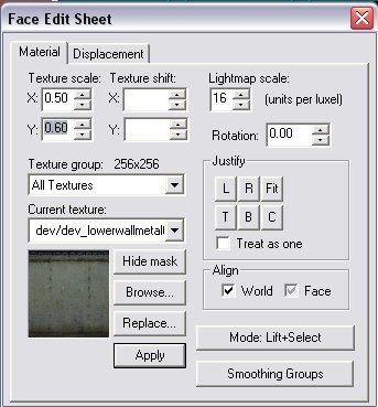
基本上我想从 Valve Hammer 创建面编辑表的功能:

When you create a brush in a 3D map editor such as Valve's Hammer Editor, textures of the object are by default repeated and aligned to the world coordinates.
How can i implement this functionality using OpenGL?
Can glTexGen be used to achieve this?
Or do i have to use texture matrix somehow?
If i create 3x3 box, then it's easy:
Set GL_TEXTURE_WRAP_T to GL_REPEAT
Set texturecoords to 3,3 at the edges.
But if the object is not an axis aligned convexhull it gets, uh, a bit complicated.
Basically i want to create functionality of face edit sheet from Valve Hammer:

如果你对这篇内容有疑问,欢迎到本站社区发帖提问 参与讨论,获取更多帮助,或者扫码二维码加入 Web 技术交流群。

绑定邮箱获取回复消息
由于您还没有绑定你的真实邮箱,如果其他用户或者作者回复了您的评论,将不能在第一时间通知您!

发布评论
评论(1)
从技术上讲,您可以为此使用纹理坐标生成。但我建议使用顶点着色器从转换后的顶点坐标生成纹理坐标。说得更具体一点(我不太了解Hammer)。
看完视频我明白你的困惑了。我想你应该知道,Hammer/Source 可能没有绘图 API 生成纹理坐标,而是在内部生成它们。
因此,您可以看到纹理投射在 X、Y 或 Z 平面上,具体取决于面部指向的主要方向。然后它使用局部顶点坐标作为纹理坐标。
您可以在将模型加载到顶点缓冲区对象的代码中或在 GLSL 顶点着色器中实现此功能(效率更高,因为计算仅完成一次)。我将向您提供伪代码:
为了使其与 glTexGen 纹理坐标生成一起工作,您必须将模型分成每个主轴的部分。 glTexGen 所做的只是映射步骤face.texcoord[i] = { s = pos.<>, t = pos.<>; }。在顶点着色器中,您可以直接进行分支。
Technically you can use texture coordinate generation for this. But I recommend using a vertex shader that generates the texture coordinates from the transformed vertex coordinates. Be a bit more specific (I don't know Hammer very well).
After seeing the video I understand your confusion. I think you should know, that Hammer/Source probably don't have the drawing API generate texture coordinates, but produce them internally.
So what you can see there are textures that are projected on either the X, Y or Z plane, depending in which major direction the face is pointing to. It then uses the local vertex coordinates as texture coordinates.
You can implement this in the code loading a model to a Vertex Buffer Object (more efficient, since the computation is done only once), or in a GLSL vertex shader. I'll give you the pseudocode:
To make this work with glTexGen texture coordinate generation, you'd have to split your models into parts of each major axis. What glTexGen does is just the mapping step
face.texcoord[i] = { s = pos.<>, t = pos.<> }. In a vertex shader you can do the branching directly.