基于 2D 图块的游戏,当我用相机放大时显示图块精灵之间的间隙?
我正在使用 D3DXSPRITE 方法将地图图块绘制到屏幕上,我刚刚添加了一个缩放功能,当您按住向上箭头时会放大,但注意到您现在可以看到图块之间的间隙,这是一些
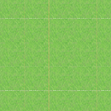
正常尺寸的屏幕截图(32x32 )每个图块

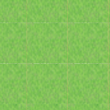
放大(您可以看到图块之间的白色间隙)

缩小(甚至最糟糕!)

这是我用来翻译和缩放世界的代码片段。
D3DXMATRIX matScale, matPos;

D3DXMatrixScaling(&matScale, zoom_, zoom_, 0.0f);
D3DXMatrixTranslation(&matPos, xpos_, ypos_, 0.0f);

device_->SetTransform(D3DTS_WORLD, &(matPos * matScale));
这是我绘制的地图,(图块位于图块向量的向量中......而且我还没有完成剔除)
LayerInfo *p_linfo = NULL;
  RECT rect = {0};
  D3DXVECTOR3 pos;
  pos.x = 0.0f;
  pos.y = 0.0f;
  pos.z = 0.0f;

  for (short y = 0;
    y < BottomTile(); ++y)
  {
    for (short x = 0;
          x < RightTile(); ++x)
    {
      for (int i = 0; i < TILE_LAYER_COUNT; ++i)
      {
        p_linfo = tile_grid_[y][x].Layer(i);

        if (p_linfo->Visible())
        {
          p_linfo->GetTextureRect(&rect);

          sprite_batch->Draw(
            p_engine_->GetTexture(p_linfo->texture_id),
            &rect, NULL, &pos, 0xFFFFFFFF);
        }
      }
      pos.x += p_engine_->TileWidth();
    }
    pos.x = 0;
    pos.y += p_engine_->TileHeight();
  }
I am using the D3DXSPRITE method to draw my map tiles to the screen, i just added a zoom function which zooms in when you hold the up arrow, but noticed you can now see gaps between the tiles, here's some screen shots
normal size (32x32) per tile

zoomed in (you can see white gaps between the tiles)

zoomed out (even worst!)

Here's the code snipplet which I translate and scale the world with.
D3DXMATRIX matScale, matPos;

D3DXMatrixScaling(&matScale, zoom_, zoom_, 0.0f);
D3DXMatrixTranslation(&matPos, xpos_, ypos_, 0.0f);

device_->SetTransform(D3DTS_WORLD, &(matPos * matScale));
And this is my drawing of the map, (tiles are in a vector of a vector of tiles.. and I haven't done culling yet)
LayerInfo *p_linfo = NULL;
  RECT rect = {0};
  D3DXVECTOR3 pos;
  pos.x = 0.0f;
  pos.y = 0.0f;
  pos.z = 0.0f;

  for (short y = 0;
    y < BottomTile(); ++y)
  {
    for (short x = 0;
          x < RightTile(); ++x)
    {
      for (int i = 0; i < TILE_LAYER_COUNT; ++i)
      {
        p_linfo = tile_grid_[y][x].Layer(i);

        if (p_linfo->Visible())
        {
          p_linfo->GetTextureRect(&rect);

          sprite_batch->Draw(
            p_engine_->GetTexture(p_linfo->texture_id),
            &rect, NULL, &pos, 0xFFFFFFFF);
        }
      }
      pos.x += p_engine_->TileWidth();
    }
    pos.x = 0;
    pos.y += p_engine_->TileHeight();
  }
如果你对这篇内容有疑问,欢迎到本站社区发帖提问 参与讨论,获取更多帮助,或者扫码二维码加入 Web 技术交流群。

绑定邮箱获取回复消息
由于您还没有绑定你的真实邮箱,如果其他用户或者作者回复了您的评论,将不能在第一时间通知您!


发布评论
评论(5)
你的纹理索引是错误的。 0,0,32,32 不是正确的值 - 它应该是 0,0,31,31。 256 像素纹理图集的从零开始的索引将产生 0 到 255 的值,而不是 0 到 256,而 32x32 纹理应产生 0,0,31,31。在这种情况下,错误像素的颜色取决于右侧和底部的下一个纹理的颜色。
Your texture indices are wrong. 0,0,32,32 is not the correct value- it should be 0,0,31,31. A zero-based index into your texture atlas of 256 pixels would yield values of 0 to 255, not 0 to 256, and a 32x32 texture should yield 0,0,31,31. In this case, the colour of the incorrect pixels depends on the colour of the next texture along the right and the bottom.
这就是放大和缩小的问题。您的纹理应该有不可见的边框,其中填充了相邻纹理的一部分。然后,放大和缩小过滤器将使用该边框来计算边缘像素的颜色,而不是默认(白色)颜色。
我想是的。
That's the problem of magnification and minification. Your textures should have invisible border populated with part of adjacent texture. Then magnification and minification filters will use that border to calculate color of edge pixels rather than default (white) color.
I think so.
我在纹理映射方面也遇到了类似的问题。对我有用的是更改采样器状态描述中的纹理地址模式;纹理地址模式用于控制 direct3d 对 ([0.0f, 1.0f]) 范围之外的纹理坐标执行的操作:我将 ADDRESS_U、ADDRESS_V、ADDRESS_W 成员更改为 D3D11_TEXTURE_ADDRESS_CLAMP,它基本上夹紧了所有超出范围的值纹理坐标进入 [0.0f, 1.0f] 范围。
I also had a similar problem with texture mapping. What worked for me was changing the texture address mode in the sampler state description; texture address mode is used to control what direct3d does with texture coordinates outside of the ([0.0f, 1.0f]) range: i changed the ADDRESS_U, ADDRESS_V, ADDRESS_W members to D3D11_TEXTURE_ADDRESS_CLAMP which basically clamps all out-of-range values for the texture coordinates into the [0.0f, 1.0f] range.
经过长时间的搜索和测试人们的解决方案,我发现这个规则是我读过的最完整的规则。
来自 Unity 官方网站的 Pixel-perfect-2d
另外根据我自己的经验我发现如果精灵PPI是72(例如),你应该尝试为该图像使用更多的PPI(也许96或更多)。它实际上使精灵更加密集,没有空间让白色间隙出现。
After a long time searching and testing people solutions I found this rules are the most complete rules that I've ever read.
pixel-perfect-2d from Official Unity WebSite
plus with my own experience i found out that if sprite PPI is 72(for example), you should try to use more PPI for that Image(96 maybe or more).It actually make sprite more dense and make no space for white gaps to show up.
欢迎来到浮点世界。这些差距的存在是由于浮点数的不完美造成的。
在进行浮点数学运算时,您可以通过非常小心来改善这种情况,但除非您从地形中创建一个完整的网格,否则这些接缝将会存在。
光栅化器给出的视图和投影矩阵以及顶点位置略有偏差。你也许可以改进这一点,但我不知道你会取得多大的成功。
您可以只索引构成地形的可见顶点,而不是绘制不同的四边形,而是使用纹理平铺技术在上面绘制不同的东西。我相信这不会给你带来丑陋的接缝,因为在这种情况下,从技术上讲,不存在接缝。
Welcome to the world of floating-point. Those gaps exist due to imperfections using floating-point numbers.
You might be able to improve the situation by being really careful when doing your floating-point math but those seams will be there unless you make one whole mesh out of your terrain.
It's the rasterizer that given the view and projection matrix as well as the vertex positions is slightly off. You maybe able to improve on that but I don't know how successful you'll be.
Instead of drawing different quads you can index only the visible vertexes that make up your terrain and instead use texture tiling techniques to paint different stuff on there. I believe that won't get you the ugly seam because in that case, there technically isn't one.